


Western Electric
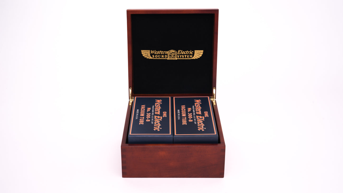
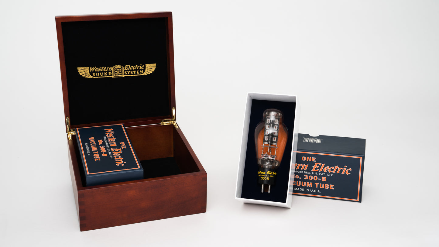
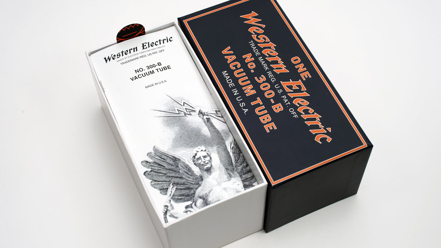
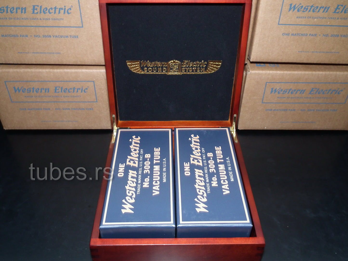
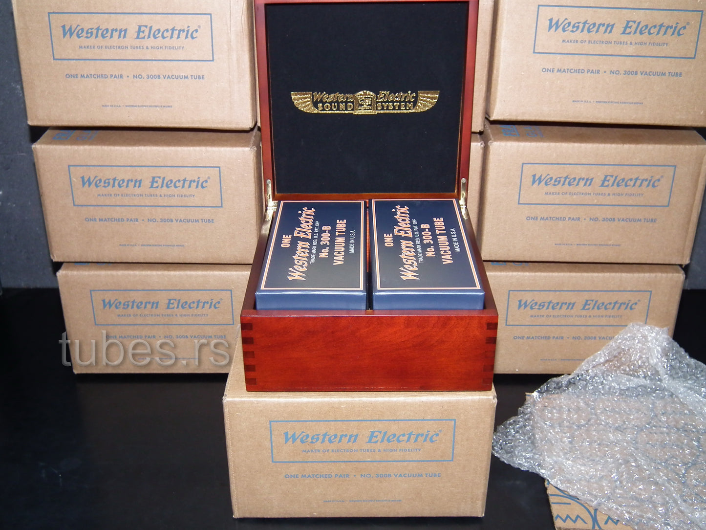
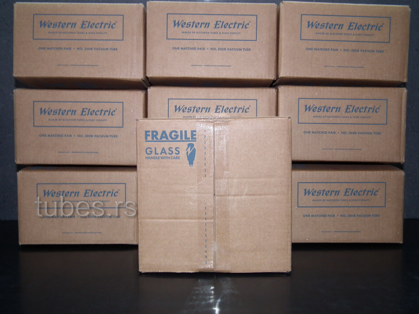
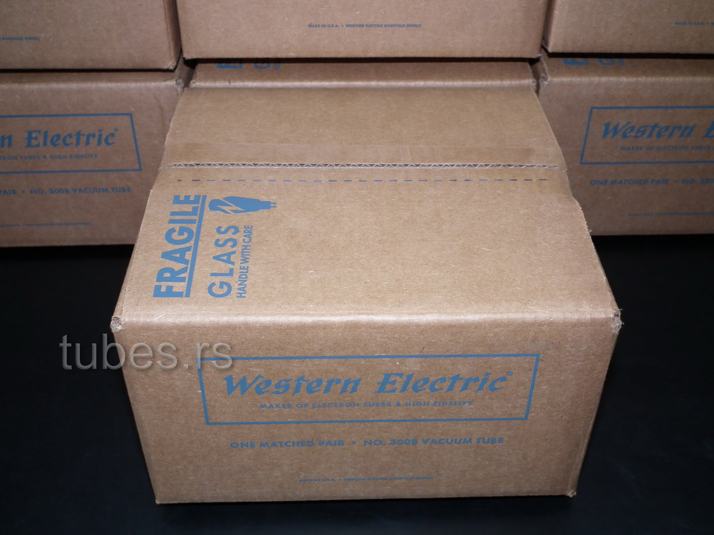
Western Electric 300B Matched Pair
Western Electric 300B Matched Pair
Regular price
€1.495,00
Regular price
Sale price
€1.495,00
Unit price
per
Tax included.
Shipping calculated at checkout.
Couldn't load pickup availability
Western Electric 300B Matched Pair
Free shipping.
For EU customers, tubes will be shipped from EU.
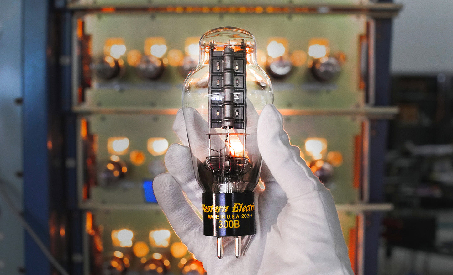
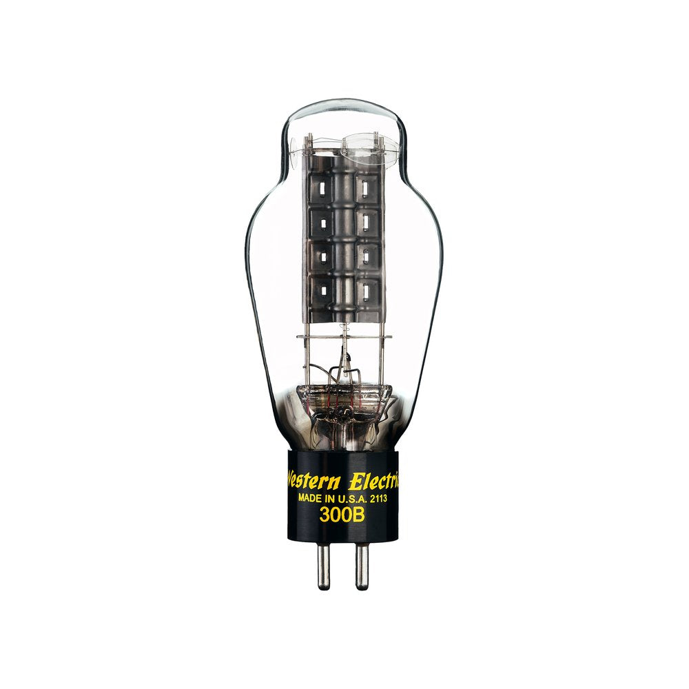
Upgrade your amplifier setup with the finest electron tube ever made. The type 300B is made by hand in the USA using the original Western Electric specifications from 1938.
Electron tubes carry a Limited Warranty of ninety (90) days to the end user. The Limited Warranty period may be extended to five (5) years upon return of warranty card included with your electron tube purchase.
Legendary WESTERN ELECTRIC 300B DH Triode
Engineered for high performance and long life
What if the best sound was achieved decades ago? In 1938, Western Electric manufactured the first type 300B electron tube. It was a breakthrough power triode, but in those days it worked behind the scenes in the projection room. It was just another component in early Hollywood sound systems. The same great things that served moviegoers in those early days—low noise, ultra-long life, sonic purity and warmth—made it a standout tube for music lovers and vintage audio collectors as decades passed. Deep into the age of the transistor, communities around the world in search of original high-fidelity rediscovered the 300B and its exceptional performance. New amplifier designs brought the tube front and center, its customary yellow lettering on proud display.
Sometimes, the old ways are the best
Today, the 300B is manufactured at the Rossville Works. Our new factory home was custom-built to master the dozens of individual demands of tube making, from sealing the iconic glass bulb to the complex metallurgic processes within. We’ve modernized the production line here and there to establish forward momentum at a company with 150 years of history. Western Electric believes twenty-first century listeners deserve twenty-first century manufacturing standards.
SPECIFICATIONS
Classification
Moderate power, filamentary triodes for Class-A service.
Application
Audio-frequency amplifier in positions where power outputs of approximately ten watts or less are required at relatively low plate voltages.
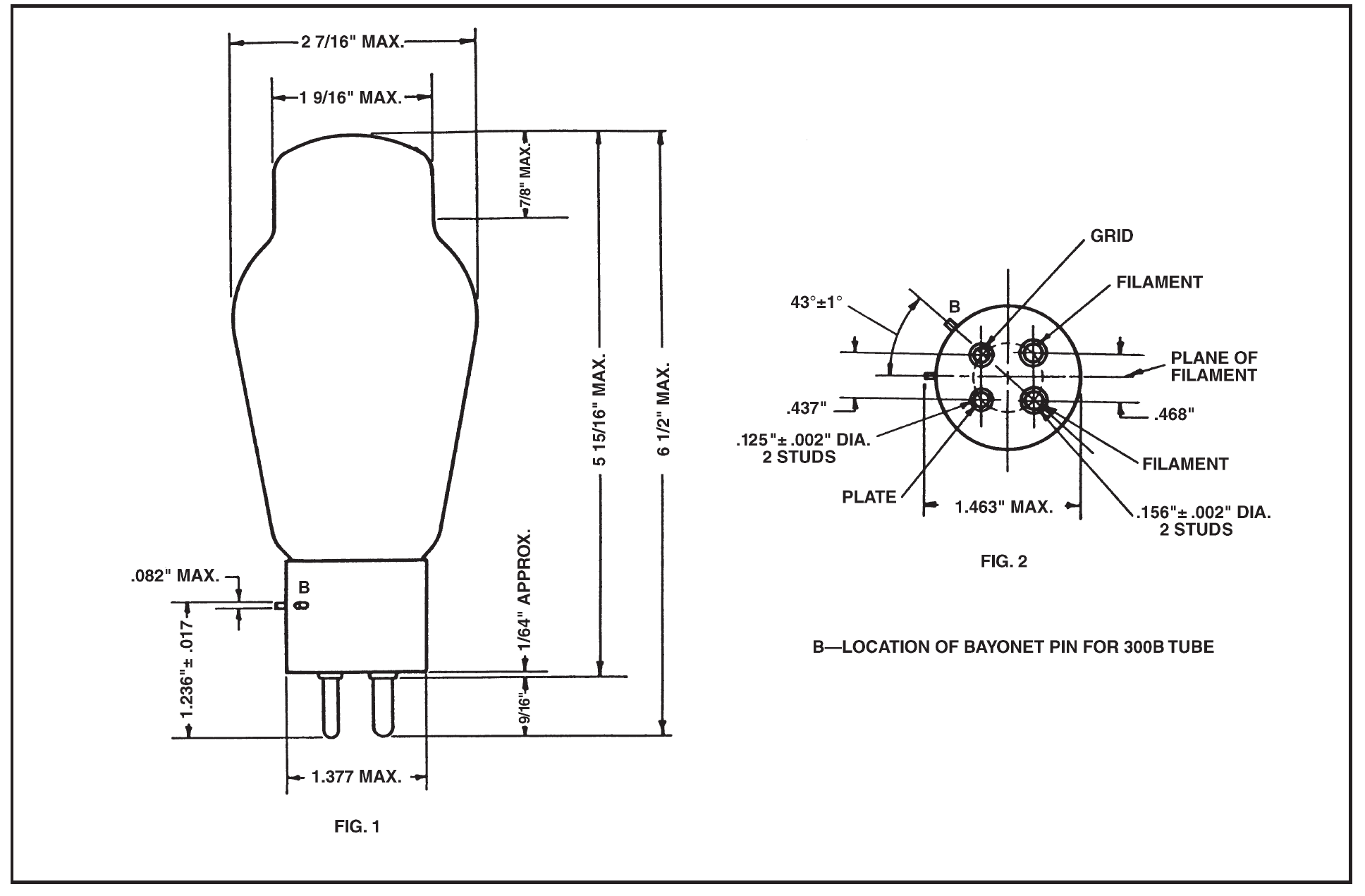
Dimensions
Dimensions, outline diagrams of the tubes and bases, and the arrangement of electrode connections to the base terminals are shown in Figures 1 and 2.
Base and Mounting
These vacuum tubes employ medium, four-pin thrust type bases suitable for use in Western Electric 143B or similar sockets. The 300B tube has the bayonet pin so located that it may also be mounted in a Western Electric 100M, 115B, or similar socket.
The tubes may be mounted in either a vertical or horizontal position. If mounted In a horizontal position, the plane of the filament, which is indicated In Figure 2, should be vertical.
Average Direct Interelectrode Capacitances
Grid to plate 15 µµf.
Grid to filament 9 µµf.
Plate to filament 4.3 µµf.
Filament Rating
Filament voltage 5.0 volts, a.c. or d.c.
Nominal filament current 1.2 amperes
The filaments of these tubes are designed to operate on a voltage basis and should be operated at as near the rated voltage as possible. When alternating current is used for heating the filament, the grid and plate returns should be connected to a center tap on the secondary of the filament transformer.
CHARACTERISTICS
Average Characteristics
(Ef = 5.0 volts, a.c., Eb = 300 volts and Ec = -61 volts)
Plate current 60 milliamperes
Amplification factor 3.85
Plate resistance 700 ohms
Grid to plate transconductance 5500 micromhos
Limiting Operating Conditions for Safe Operation
(Not simultaneous ratings)
Maximum plate voltage: 450 volts
Maximum plate dissipation: 40 watts
Maximum plate current of an average tube for fixed grid bias: 70 milliamperes
Maximum plate current for manually adjusted grid bias or self-biasing circuit: 100 milliamperes
Recommended Operating Conditions
Recommended and maximum conditions for alternating-current filament supply are given in the table. Recommended conditions or others of no greater severity should be selected in preference to maximum conditions wherever possible. The life of the tube at maximum operating conditions will be shorter than at the recommended conditions.
Where it is necessary to operate the tube at or near the maximum plate current of 100 milliamperes, provision should be made for adjusting the grid bias of each tube independently, so that the maximum safe plate current will not be exceeded in any tube. Alternatively, a self-biasing circuit may be used, in which the grid bias for the tube is obtained from the voltage drop produced by the plate current of that tube flowing through a resistance.
Where it is necessary to use a fixed grid bias, the plate current of the average tube should be limited to a maximum value of 70 milliamperes, so that tubes having plate currents higher than the average will not exceed the maximum safe plate current.
Power Output and Distortion
Performance data including power output, second and third harmonic levels for a number of operating conditions are given in the table.
The variation of power output and harmonic levels with load resistance for several values of operating plate current is shown in Figures 7, 8 and 9, for a plate voltage of 350 volts.
The peak value of the sinusoidal input voltage, Egm, which gives the indicated power output, Pm and harmonic levels, F2m and F3m for each point in both the curves and the table, is numerically equal to the grid biasing voltage at that point. For a smaller input voltage Eg, the approximate levels may be computed from the following relations.
P=Pm(Eg/Egm)^2
F2=F2m+20 log10(Eg/Egm)
F3=F3m+40 log10(Eg/Egm)
CHARACTERISTIC CURVES
Plate-current characteristics for a typical tube are shown in Figure 3 as functions of grid bias, for alternating-current filament supply. The corresponding amplification-factor, plate-resistance, and transconductance characteristics are given in Figures 4, 5 and 6, respectively. When direct-current filament supply is used, and the grid and plate returns are connected to the negative end of the filament, the same characteristics are applicable if 3.5 is subtracted from the numerical value of each grid bias.